

1. Mission Context & Transport Imperative
In modern joint and coalition operations, the speed and integrity of data movement are nonnegotiable. From persistent ISR platforms streaming high-resolution video, to sensor arrays injecting terabytes of data, to maneuver units depending on command and control loops — the transport fabric must meet the challenge. In many operations, the “last mile” or tactical edge becomes the chokepoint: 5G or RF links may suffice for control, but bulk data must traverse fiber or space-aware channels. Failing to close that gap means operations stall, decisions degrade, and risk increases.
The core challenge: RF/5G channels are limited, contested, and vulnerable to jamming or denial. Optical fiber backbones offer massive capacity but are vulnerable to cuts or natural disasters. Satellite lasercom offers high throughput and agility but must deal with atmospheric disruption and orbital constraints. The key is not choosing one over the others — it’s integrating all three into a unified fabric.
Transport must be dynamic, not static. Tactical operations shift on hours’ notice. A solution architected today must reconfigure tomorrow in response to damage, interference, or shifting priority. That demands not just physical layers, but control logic, orchestration, and intelligent routing.
Over the past several years, the Department of Defense has moved in this direction. The DoD Private 5G Deployment Strategy envisions private and hybrid 5G networks integrated with mission assets and resilient backhaul. Department of Defense CIO Likewise, the SDA’s Optical Communications Terminal (OCT) standards aim for interoperable, agile optical nodes in space and ground. sda.mil And the CCSDS committees continue refining optical communications standards via their 141.x families. ccsds.org+1 These evolving standards and programmatic thrusts create an enabling environment — but successful deployment requires bridging theory and practice.
In the following sections, we explore how to integrate 5G, fiber, and lasercom, walk through performance models, present a detailed case study, and conclude with acquisition and architecture recommendations.
2. 5G Tactical Edge: Role, Performance, and Limitations
2.1 Tactical 5G in the DoD Context
At the tactical edge, 5G fills a critical connectivity role: it aggregates sensors, unmanned systems, local computing nodes, and simplifies local command traffic. It provides a wireless last hop where fiber cannot reach. The DoD’s strategy for private 5G builds on this, emphasizing modular, secure, mission‑aligned 5G infrastructure across installations and forward areas. Department of Defense CIO+1 In addition, defense-focused packages are emerging: Nokia recently introduced a rugged “network-in-a-box” system combining hardened radio and handset hardware for field deployments. TeckNexus
3GPP standards define the architecture and features. Release 15 introduced foundational 5G NR; subsequent releases add URLLC (Ultra-Reliable Low Latency Communications), network slicing, and edge computing support — features essential to mission-critical applications. 3GPP+1
2.2 Performance Modeling & Failover Dynamics
Though we will not place full equations here, the conceptual model is: link throughput, latency, and failover behavior must be well understood. In many tactical 5G designs, handover latency (detection, signaling, reconnection) is 10–100 ms in good conditions. That window is sufficient for maintaining ISR video continuity under cell loss.
Latency on the 5G path includes propagation, radio scheduling, and core network traversal. In practice, for short-range tactical cell hops, propagation and scheduling dominate.
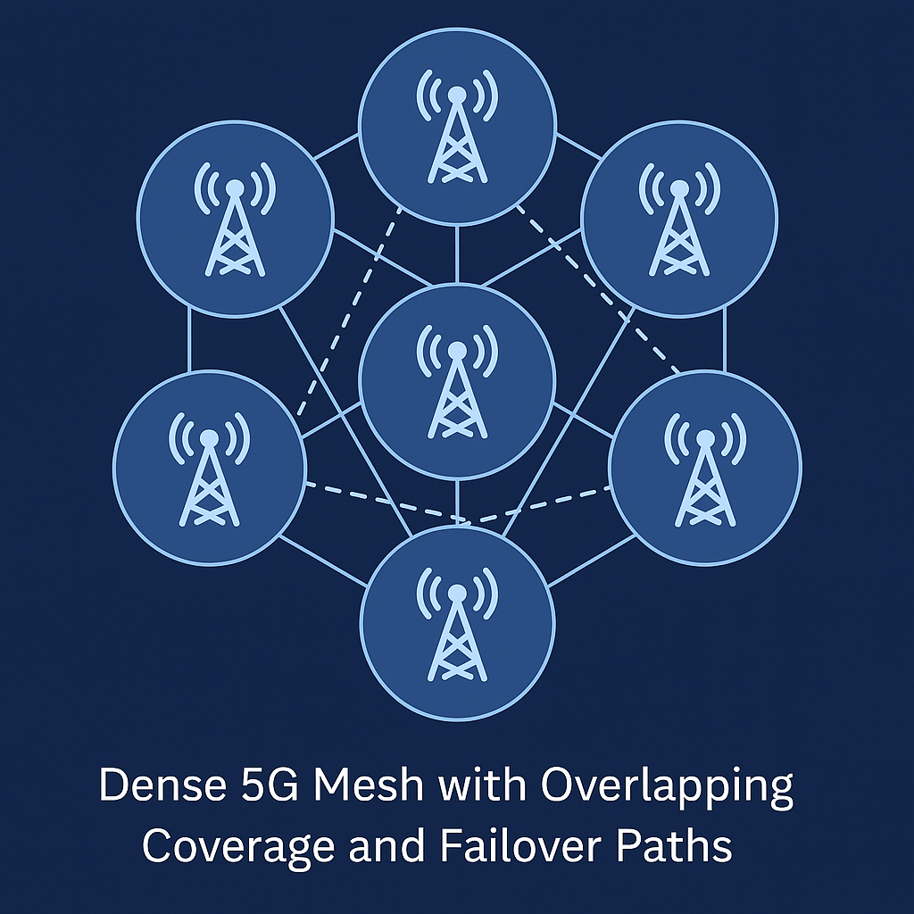
However, 5G faces vulnerabilities: base station losses, power outages, hardware attack, or jamming can disable nodes. Because 5G nodes are relatively exposed, densification (overlapping cells, mobile relays) is mandatory for resilience. The network must allow devices to roam or reconnect automatically.
2.3 Plain-English Summary
Tactical 5G is indispensable at the edge — it enables wireless aggregation, mobility, and flexibility. But it must be deployed with redundancy, fast handoff, and a fallback path so that if one cell is compromised, connectivity persists.
3. Optical Backbone: Fiber as the High-Capacity Engine
3.1 Architecture & Standards
Optical fiber remains the backbone of modern high-capacity networks. DWDM (Dense Wavelength Division Multiplexing) allows dozens to hundreds of wavelengths over a single fiber — each potentially 100 Gb/s, 400 Gb/s, or more. Network designs also incorporate Optical Transport Network (OTN) layers, error-correction and grooming, and automated optical switching.
Standards frameworks like IEEE/ITU (e.g. IEEE 802.3, ITU‑T G.709) support interoperability of optical transport. In coherent optics and advanced modulation, OpenZR+ provides a standards-based interface for coherent optical links.
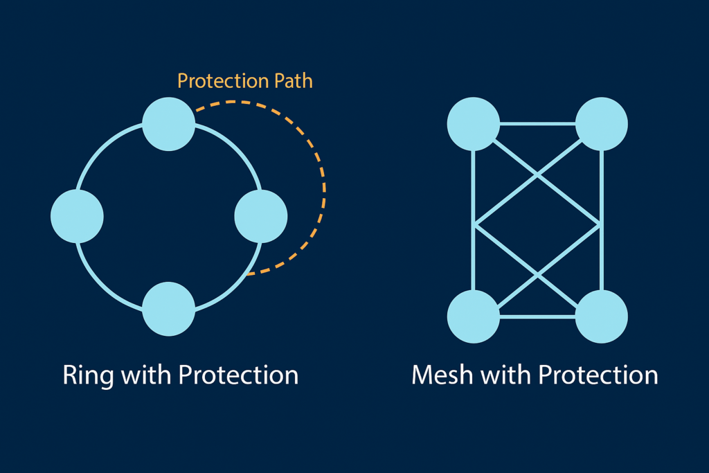
In defense deployments, fibers are laid in protected routes, often multiple diverse paths, deep burial, or underground conduits. Redundancy is achieved through ring or mesh topologies, enabling alternate routing when one span fails.
3.2 Protection Switching & Recovery Time
In optical networks, fast protection switching is key to resilience. ITU‑T G.841 and G.803 define protection schemes, such as 1+1 (dedicated protection), 1:1, or shared protection. G.841, notably, establishes that protection switching must occur within 50 ms or less, triggered by loss or signal degradation.
When a span fails, the network automatically reroutes affected wavelengths to the alternate direction (in ring) or across mesh detours. The failover is transparent to higher-layer traffic, with minimal packet loss.
Fiber’s advantages are compelling: ultra-low latency, extremely high throughput, mature technology, and low error rates. Still, fiber bears risk: cuts, natural disasters, vandalism, or excavation can disrupt service.
3.3 Plain-English Summary
Fiber gives the network the capacity to absorb massive data flows. In a resilient design, when one fiber span fails, optical switches route traffic around the cut in under 50 ms, preserving mission data delivery.
4. Satellite Lasercom: Linking Beyond the Terrestrial Domain
4.1 Architecture & Standards
Laser communications in space and between satellite-ground nodes offers massive bandwidth, low detectability, and path diversity. The CCSDS 141.x series defines the physical and link-layer protocols for space optical communications. ccsds.org+2NASA Technical Reports Server+2 These standards govern modulation, synchronization, error correction, and interoperability between satellite and ground terminals.
SDA’s Optical Communications Terminal (OCT) standards are pushing for interoperable space-to-ground optical nodes in national defense architectures. sda.mil ESA’s ESTOL (Terabit Optical Links) initiative also defines agnostic inter-satellite and ground link specifications. ESA CSC
Optical terminals often operate in the 1550 nm band, using coherent modulation and channel coding to support data rates up to 100–400 Gb/s or more per link. MathWorks
4.2 Reroute Delay & Resilience
When a path is compromised — for example, an optical ground station is obscured by weather — the system must steer optical beams, engage alternate crosslinks, and converge link algorithms. The total delay comprises propagation plus reconfiguration overhead:

Typical numbers: propagation ~3–10 ms per thousand kilometers; reconfiguration (beam steering, routing convergence) ~10–100 ms. In practice, reroutes may take 20–120 ms, though advanced systems aim for lower latency.
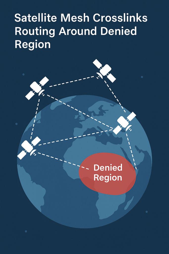
Because optics is path-limited (line-of-sight), satellites can form mesh crosslinks to route around denied regions — bypassing ground interference or outage zones entirely.
4.3 Plain-English Summary
Satellite lasercom adds a path outside terrestrial constraints. When ground links fail, optical crosslinks re-route data across space, often within 100 ms, preserving continuity even in contested terrain.
5. Hybrid Mesh & Integrated Failover Modeling
5.1 Hybrid Mesh Architecture
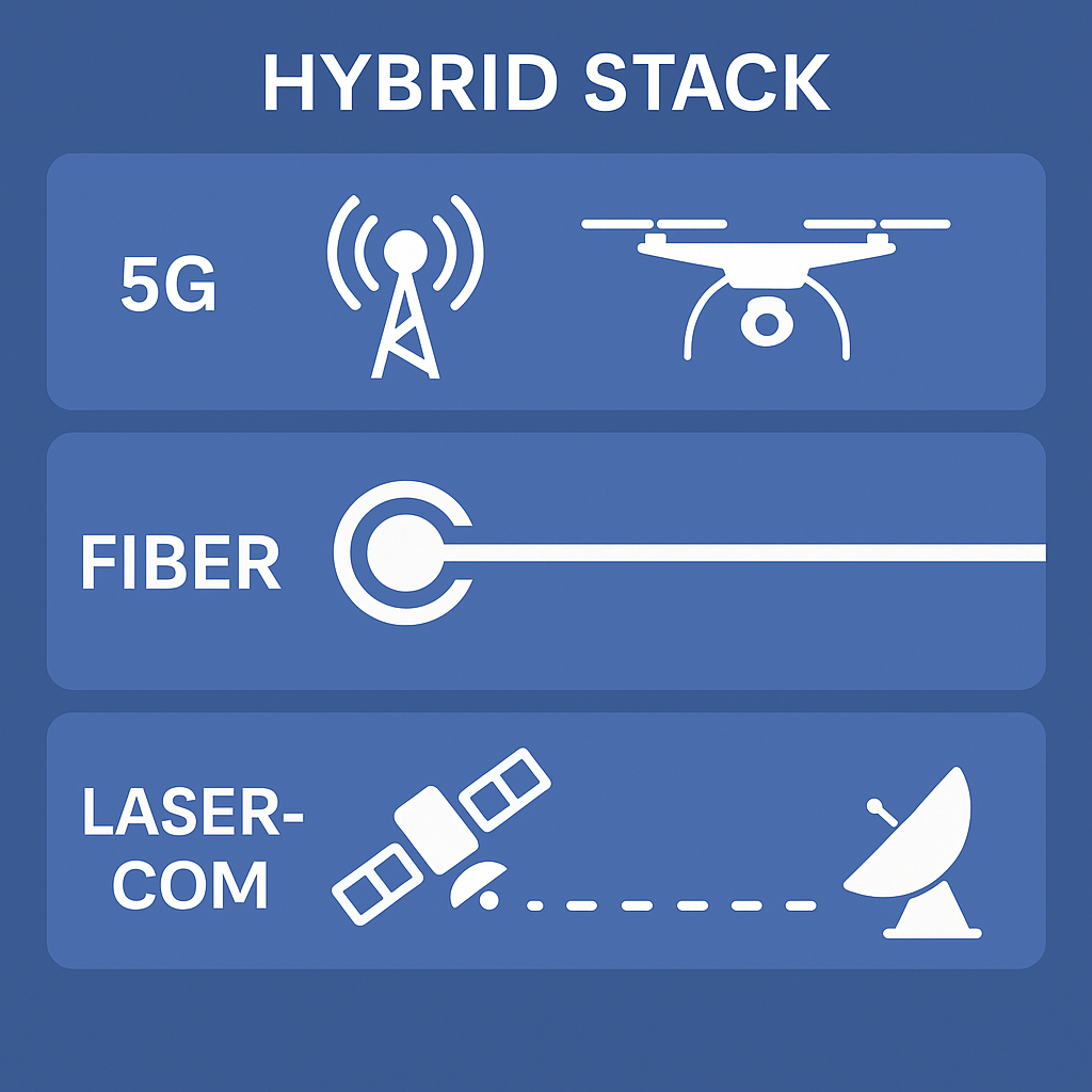
A fully resilient transport architecture is hybrid: 5G at the edge, fiber for core backhaul, and lasercom for global extension. Traffic flows may take multiple paths:
- Sensor → 5G → fiber → CONUS hub
- Sensor → 5G → lasercom crosslink → remote OGS → fiber
- C2 traffic → low-latency 5G or optical slice
Orchestration — whether via SDN or control-plane logic — must dynamically select the optimal path given latency, threat, and mission weight.
5.2 Failover Comparison & Modeling
We compare failover delays across domains:
| Failure Mode | Fiber Protection | 5G Handoff | Lasercom Reroute |
| Fiber cut | ≤ 50 ms | — | — |
| 5G cell loss / jamming | — | ~10–100 ms | — |
| OGS outage / path blocked | — | — | ~20–120 ms |
Because all domains can act in sub‑0.2 second windows, the hybrid mesh can absorb multi-domain failure with minimal impact.
5.3 Traffic Prioritization & Allocation
Within the mesh, not all traffic is equal. A weighting system can allocate bandwidth based on mission priority: ISR > C2 > administrative. For example, if capacity is 100 Gb/s and weights are 0.6, 0.3, 0.1, allocations become 60, 30, 10 Gb/s. This ensures mission flows remain prioritized under congestion or failover.
5.4 Plain-English Summary
The hybrid mesh behaves like a multi-layer freeway: high-volume traffic rides optical express lanes, while control traffic remains on low-latency reserved links. If one route fails, traffic reroutes instantly across domains with no manual intervention.
6. Case Study: Coastal Surveillance in a Contested Theater
A joint force conducts coastal surveillance in a contested littoral environment. Drones stream 300 Gb/s of electro-optical video. Coalition partners exchange mapping and ISR data at 50 Gb/s. Command nodes communicate low-latency control flows.
During an adversary escalation:
- A submarine operation severed a regional undersea fiber link.
- Jamming disrupted RF/5G coverage across one island cluster.
- A storm obscured the regional optical ground station.
Mesh response:
- Immediately, the fiber protection mechanism reroutes traffic via alternate rings (≤ 50 ms).
- ISR devices lose 5G coverage but find overlapping cells; handover completes in ~70 ms.
- Optical downlink shifted to alternate OGS via crosslinks; reroute delay ~80 ms.
Net result: data continues flowing with <200 ms added latency relative to nominal. Analysts receive imagery, command nodes maintain continuity, and coalition link persists at reduced rate — all seamlessly.
This example illustrates how multi-domain dynamic routing preserves mission flows even under simultaneous threats.
7. Acquisition, Standards & Recommendations
To realize this hybrid mesh, procurement and architecture choices must align with standards and resilience requirements.
7.1 Standards & Interoperability
- ITU‑T G.841 / G.803: Optical protection switching standards.
- IEEE/ITU DWDM / OTN / Ethernet (802.3 / G.709).
- OpenZR+: Ensures coherent optics interoperability.
- 3GPP (NR, URLLC, slicing).
- CCSDS 141.x / 142.x: Optical communications protocols. ccsds.org+2ccsds.org+2
Industry must commit to open interfaces and avoid proprietary traps (e.g. closed lasercom or 5G stacks). Concerns exist: for example, Starlink’s proprietary lasercom terminals being unverified for SDA/CCSDS compatibility raise interoperability risk. kratosspace.com
7.2 Acquisition Strategy
Contracts should include failover metrics, reconfiguration latency caps, and multi-domain routing requirements. Programs like DISA transport modernization, SDA optical mesh, and JADC2 architecture must embed hybrid transport requirements, not treat optical or 5G as add-ons.
7.3 Roadmap
- Develop hybrid testbeds that integrate 5G, fiber, lasercom, and orchestration layers.
- Run disruption campaigns to validate cut, jamming, and weather scenarios.
- Train operators in dynamic-mesh operations.
- Mature open interoperability standards and enforce them in RFPs.
8. Conclusion
The “transport gap” between tactical 5G and core optical networks is no longer acceptable in contested missions. Bridging that gap demands a resilient hybrid mesh — combining 5G, fiber, and satellite lasercom — managed by dynamic orchestration.
This integrated architecture can withstand fiber cuts, jamming, and optical path disruptions, rerouting traffic in tens of milliseconds to preserve ISR and C2 integrity. The underlying standards — from G.841 for fiber switching to CCSDS optical protocols — are mature and evolving. DoD initiatives (Private 5G, SDA, DISA modernization, JADC2) already point in this direction.
The path forward requires acquisition discipline, open standards compliance, and early adoption of testbeds. The future battlefield will not wait — transport must match mission pace.
Lightwave Analytics supports U.S. government and industry partners with advanced modeling, acquisition support, and technical analysis for optical communications — from satellite lasercom to terrestrial fiber networks.
We support government programs and industry teams with deep-domain expertise and mission-aligned insight.
📄 Download our capability statement